Test rig and dynamometer frames: what the drawing must say
By Ryan, independent sourcing agent, Ho Chi Minh City, Vietnam
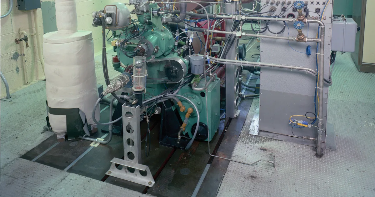
A test rig frame is the quietest component in the test cell and the easiest to underspecify. It does not move, it has no electronics and its drawing is often a sketch with a plate thickness and a bolt pattern. Yet every measurement the rig makes passes through it: torque reaction, vibration, alignment and the sound of the machine it carries.
A frame that flexes between the unit under test and the dynamometer misaligns shafts and wastes torque in bending. A frame that resonates at an engine order corrupts vibration data. This article describes what a drawing for a test rig or dynamometer frame must say so that a partner shop builds it, and so that it performs once it is in the test cell.
What the frame has to do
Carry static loads. The weight of the unit under test, the dynamometer, couplings, guards and fluids sets the static load. Machines in the few-hundred-kilogram to several-tonne range need load paths that reach the foundation without large deflections.
Resist torque reaction. A dynamometer absorbing 500 N·m pushes back on its mounting with 500 N·m. Whether the machine is cradled, with a load cell measuring reaction torque, or foot-mounted, the frame must carry that moment without rotating or twisting measurably. Twist of the frame between the two machines changes shaft alignment under load.
Hold alignment. The shafts of the unit and the dynamometer must stay coaxial and parallel within the coupling’s tolerance. Typical targets are a few hundredths of a millimetre of offset and similar angular tolerance, tighter at high speed. The frame sets the starting point and must not creep.
Avoid resonance. Rotating machines excite the structure at the shaft speed and its multiples. The frame’s natural frequencies should not coincide with them across the speed range of the test. The theory is in natural frequency of machine structures.
Contain failure. Rotating parts can fail at speed. The frame, guards and floor mounting need to be designed to withstand the energy of a broken coupling or shaft within safety standards.
Set the frequency target from the test speed range
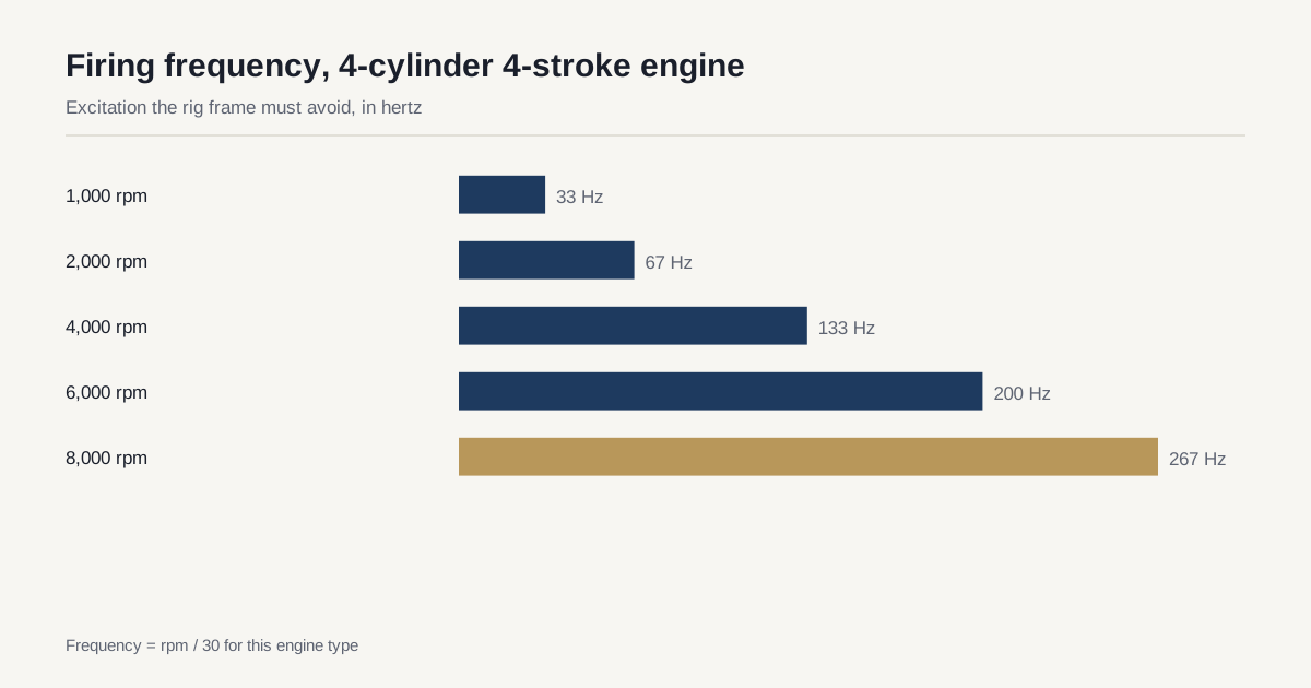
The simplest way to find the excitation range is to look at the test speeds. A four-cylinder, four-stroke engine fires twice per revolution, so its firing frequency in hertz equals the speed in rpm divided by 30:
| Engine speed | Firing frequency (4-cylinder, 4-stroke) |
|---|---|
| 1,000 rpm | about 33 Hz |
| 2,000 rpm | about 67 Hz |
| 4,000 rpm | about 133 Hz |
| 6,000 rpm | about 200 Hz |
| 8,000 rpm | about 267 Hz |
Electric machines excite at the rotor speed and at tooth and slot frequencies, which are higher. For a test across a wide speed range, no frame can avoid every excitation. Two strategies are common: place the frame’s first natural frequency well above the maximum excitation, typically at least 1.5 to 2 times higher, or place it below the lowest operating speed so that the test passes through no resonance. Write the target as a number on the drawing or in the specification, along with the loading condition it applies to, such as the machine mass on the frame.
What the drawing must say
| Item | What to write | Typical value or note |
|---|---|---|
| Loads | Mass and position of each machine, rated and peak torque, maximum speed | Give both normal and short-circuit or fault torque for electrical machines |
| Interface flatness | Flatness of mounting pads or T-slot plate, with datum | Often 0.05 to 0.1 mm over the mounting area |
| Hole positions | Position of mounting holes relative to a datum | Within 0.1 mm if machines bolt directly |
| Shaft height | Height of shaft centreline above the base datum | Tolerance of a few tenths of a millimetre, with shim allowance |
| Coplanarity | Coplanarity of all feet for one machine | Within 0.05 mm before shimming |
| Natural frequency | First mode target and loading condition | Number in hertz |
| Material | Grade, delivery condition and certificates | See mill certificate types |
| Welding | Joint types, quality level, NDT on torque path and lifting points | See NDT for machine frame welds |
| Stress relief | Required or not, and cycle | Needed if pads are machined to tight flatness |
| Fluid and electrical | Drip tray, drain, earth bonding points | Oil-resistant paint, a clear earth path |
| Lifting and transport | Lifting points with rated capacity, centre of gravity | Mark on the drawing |
| Anchoring | Foundation bolts, grout or chemical anchors | Interface with the cell builder |
The values are typical. The numbers that matter are the ones that follow from your alignment budget and coupling data.
Alignment features worth designing in
Alignment is easier if the frame provides adjustment, so the shop need not hit the geometry by luck.
- Jacking screws on each foot pad let the installer move a machine in height and in plane without crowbars.
- Shim space. Leave 2 to 3 mm of space under each foot, for shims, so that alignment can be refined on site.
- Dowel holes or locating pads for repeat installation of the same machine.
- A machined reference surface on the frame for the installer’s laser alignment tool or dial indicators.
Alignment tolerances accumulate through the frame, shims and couplings. The method for working that out is in machine frame tolerance stack-up.
Thick plate, ribs and torque path
Torque reaction passes through a specific path in the frame: from the foot pads through the pad plate, into ribs or box walls and down to the base. That path deserves heavier plate, full penetration welds where the load is through the plate and clear continuity of ribs under each foot. The choice between weld types is covered in fillet or full-penetration welds.
Open frames of channel or angle are lighter, but twist more under torque. Boxed bases and thick pads suit high-torque rigs. Mounting plates machined after welding give a flat interface, and large pads should be stress relieved first. See stress relieving welded machine bases.
Inspection records for a rig frame
For a frame that will be used in measurements, evidence matters. A useful record includes:
- Dimensional report on pad flatness, hole positions and shaft height, with the support condition. Dimensional reports on weldments explains how to specify it.
- Material certificates and heat numbers.
- NDT reports on the torque path and lifting points.
- Photographs before painting.
- Frame mass, as built, for the rig’s modal model.
Safety and containment
A rig that spins an engine or motor to high speed stores energy in the rotating parts. If a coupling or shaft fails, that energy goes somewhere. The frame, guards and floor fixings should be designed so the failure stays inside the cell. Specify the rotating mass, the maximum speed and the credible failure case, and ask the shop to confirm which parts of the frame carry guard loads. Fixings into concrete need design checks of their own. Where a test cell is regulated, the safety case belongs to the rig designer, and the frame supplier’s job is to build what the safety case drew.
Documentation that helps the test lab
A rig frame will be used by people who did not design it. Supply a short document with the frame: the drawing revision, the as-built mass, the lifting instructions, the torque rating of the mounting points, the natural frequency target and the alignment procedure. If the lab runs accredited tests, the document also supports the traceability of the setup. A one-page data sheet attached to the frame, or stored with the rig records, is cheap to write at the time of building and costly to reconstruct years later.
Checklist
- State machine masses, torques and speed range on the drawing.
- Set a natural frequency target relative to the excitation range.
- Specify pad flatness, coplanarity, hole positions and shaft height with datums.
- Add jacking screws, shim space and locating features.
- Mark lifting points and the centre of gravity.
- Require NDT on the torque path and lifting points.
- Define the inspection record format before fabrication.
To check that a drawing is complete before it goes to shops, send it through the RFQ page. The network replies within 24 business hours with questions and quotes.
Have a frame drawing to price?
Send it through for a manufacturability review and a matched quote from the heavy-fabrication network. Reply within 24 business hours.