Dimensional reports on weldments: CMM, laser tracker or tape
By Ryan, independent sourcing agent, Ho Chi Minh City, Vietnam
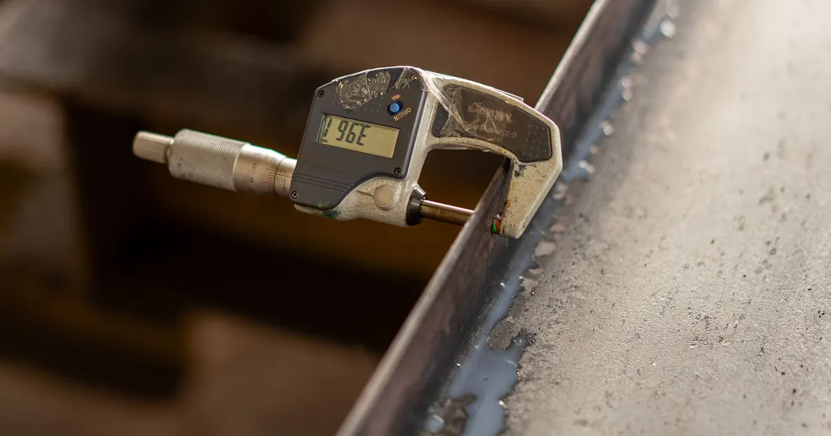
A dimensional report is a piece of paper that says a frame is the size you ordered. Whether you should believe it depends on the tool behind it. A tape measure, a laser tracker and a gantry CMM can all produce a table of numbers with a pass or fail column, and they do not produce equally trustworthy tables.
Buyers who work with welded frames from overseas partner shops need a way to judge a report quickly. This article lays out how the measuring methods differ, how measurement uncertainty relates to your tolerance, how reports should be set up and what to request in the RFQ. The report feeds the first article step in our guide to machine frame fabrication sourcing.
Match the tool to the tolerance
The first question is how tight the tolerance is compared with what the tool can resolve. Metrology practice uses a rule of thumb that the measuring system should be several times better than the tolerance it checks, commonly four to ten times. A tape that is good to 0.4 mm over 3 metres cannot verify a 0.5 mm tolerance. It can only verify tolerances of a couple of millimetres.
That matters because welded frames carry two quite different classes of tolerance:
- As-welded dimensions, usually in the range of 1 to 3 mm, governed by a general tolerance standard such as ISO 13920 or by the drawing.
- Machined features, usually 0.02 to 0.2 mm, produced after welding and stress relief.
Different tools suit each class. Tape and calipers are fine for the first. The second needs a coordinate measuring system.
The main methods
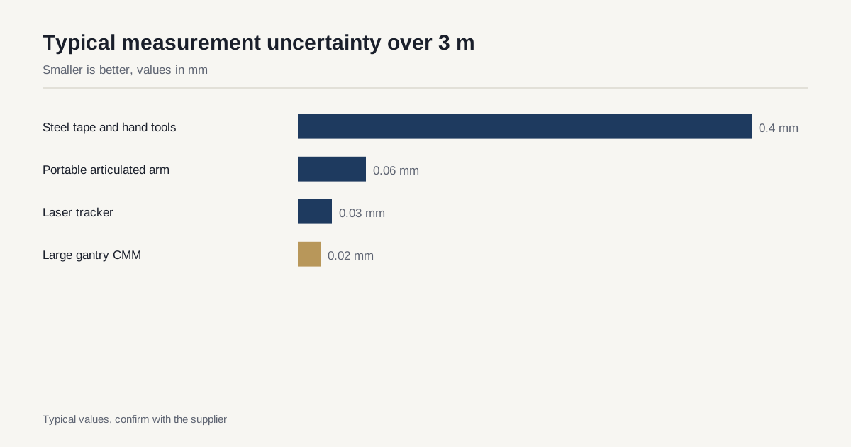
| Method | Typical uncertainty over 3 m | Typical use on frames | Report type |
|---|---|---|---|
| Steel tape and hand tools | about 0.4 mm | As-welded overall dimensions | Hand-filled table |
| Portable articulated arm | about 0.06 mm | Hole patterns, mounting faces | Table plus graphical report |
| Laser tracker | about 0.03 mm | Large frames, datum alignment | 3D report, colour map |
| Large gantry CMM | about 0.02 mm | Machined frames within its envelope | Full GD&T report |
The numbers are typical, and every instrument has its own calibration certificate. Class I steel tapes follow a tolerance formula of roughly 0.1 mm plus 0.1 mm per metre, which gives about 0.4 mm at 3 metres before any human reading error is added. A tracker’s stated accuracy depends on distance and on how the reflector is held.
Steel tape and hand tools serve the early stages of fabrication. They check cut length, overall width and diagonals before welding. They are the right tool for a general-tolerance check and the wrong tool for anything near a hole pattern or mounting face.
Portable arms are flexible and easy to move around a frame on the shop floor. Their reach limits the volume covered from one set-up, so measuring a long frame means repositioning the arm and stitching measurements, which adds uncertainty.
Laser trackers measure a large volume from one set-up and are the common choice for frames above a couple of metres. They give 3D coordinates of every point touched.
CMMs produce the most accurate results but only for parts that fit inside the machine. Machined frame castings and welded bases up to a few metres do fit on large gantry machines at some facilities. Not every partner shop has one.
Datum alignment: where reports mislead
The most common reporting trap is a best-fit alignment. Software can shift and rotate the measured points to minimise the total deviation from the CAD model. That produces an attractive colour map in which deviations look small, because the software has hidden any overall shift or twist. A frame whose mounting faces are twisted by 0.5 mm relative to the base datum can look nearly perfect under best fit.
The alternative is a datum-based alignment that follows the drawing: first the primary datum plane, then the secondary, then the tertiary, exactly as the GD&T frame states. That reproduces what you will see when the frame is bolted to a machine. For a frame whose job is to hold something in position, ask for datum-based alignment. The principles of choosing datums are in GD&T datum strategy for weldments.
What a usable report contains
- Part number, revision, serial number and date.
- Instrument type, serial number and calibration due date.
- Ambient temperature and soak condition of the frame.
- Support condition during measurement. See frame flatness and squareness checks.
- Alignment method: datum-based or best-fit, with the datum feature definitions.
- A table of characteristics: nominal, tolerance, measured, deviation and pass or fail.
- Measurement uncertainty, or at least the instrument specification.
- The name and signature of the person who measured.
An unlabelled colour map with no table, no alignment note and no instrument record is a picture, not a report.
Who measures, and when
Inspection should happen at defined points, not only at the end.
- Incoming material and cut parts. Plate thickness and cut size, by hand tools.
- After fit-up and tack, before welding. Overall geometry and diagonals, so errors are caught before heat is applied.
- After welding and stress relief. Overall geometry and allowance check before machining.
- After machining. Full dimensional report against the drawing.
- Before crating. A final check of critical characteristics and a photographic record.
A first-article routine applies the full report to the first unit and a reduced set to later units. First article inspection for large weldments describes how to choose which characteristics repeat.
Sampling on repeat orders
On a run of identical frames, measuring everything on every unit is rarely necessary. A common plan measures all characteristics on the first unit, then a defined subset, the characteristics marked critical on the drawing, on every unit and the full set on every fifth or tenth. Decide the plan before the order starts, and write it into the purchase order so nobody has to negotiate it later.
Writing it into the RFQ
Put the inspection requirement where quotes can price it:
- State which characteristics are critical and need a measured value reported.
- Name the alignment method and datum structure.
- State the inspection points and whether you or a third party will witness any of them.
- Ask the shop to name the instrument it will use for each critical characteristic.
- Ask for an example report from a similar job, with the customer details removed.
The RFQ structure in machine frame RFQ template has a section for inspection requirements that you can copy.
A note on third-party inspection
For a first order, or for a frame whose failure would be costly, a third-party inspector can verify the report. The inspector can witness the measurement at the shop, review the calibration records and sign the report. This costs money and adds scheduling, so it is usually reserved for first articles and for critical deliveries. Name the scope in the purchase order: which characteristics, which instrument, which datum. An inspector who is told only to check dimensions will check what is convenient, and not necessarily what matters to your assembly.
Why the first report is the benchmark
Treat the first dimensional report as a baseline for the whole programme. It shows how the shop’s process behaves on your geometry, which features drift and which stay put. When the next frame arrives, compare it with that baseline instead of judging it only against the drawing. A small, steady offset that appears on every unit points to a fixture or a program that needs adjusting. A random scatter points to process variation. Both are easier to see when the reports share a format, so ask the shop to keep the same layout and datum structure from the first unit onward.
Checklist
- Match instrument capability to the tolerance: tape for millimetres, tracker or CMM for hundredths.
- Ask for datum-based alignment on functional frames.
- Require a table of values, not only a colour map.
- Request instrument calibration status and ambient temperature on every report.
- Agree the sampling plan for repeat orders in advance.
- Keep the first-article report as the reference for later units.
For a frame where inspection scope is still open, send the drawing with your critical characteristics marked. Partner shops reply within 24 business hours with the instrument they would use for each one.
Have a frame drawing to price?
Send it through for a manufacturability review and a matched quote from the heavy-fabrication network. Reply within 24 business hours.